District heating contains a large network of pipes that connected the heat generating units to the storage units and subsequently transferring the hot water or steam from storage units to the end consumers’ house substations. District heating consists of the following major components in its network:
District heating offers a preferable platform for the use of highly efficient heat and power cogeneration (CHP) and use of renewable energies or waste heat. If enough heat demand is bundled by the district heating system, the principle of cogeneration can be applied with fossil fuels as well as with renewables like biomass and geothermal energy. In case of smaller units, solely heat generating plants like wood chip boilers and solar thermal plants offer a better performance than in case of single house units. Because of its importance in the following sections the principles and basics of combined power and heat (CHP) generation are first described in greater detail. After this, a short text deals with plants which generate both heat and cooling. Furthermore, a brief description of heat sources based on renewable energy but without making use of CHP is offered.
The level of combined heat and power (CHP) generation within district heating schemes should be as high as possible. The primary energy saving and CO2 reduction of CHP is especially influenced by the power efficiency of the CHP process. The power efficiency of CHP mostly depends on the chosen technology and the capacity of the unit and can be as high as 50 % (in full CHP mode). Therefore a modern technology and large capacities of district heating systems should be aspired.
Combined heat and power (CHP)
The principle of combined heat and power generation (CHP) means to convert the waste heat of power plants (heat of flue gas, the cooling loop and the lubricating oil in case of engines) to useful heat. In comparison to the application of a heat only boiler, the use of waste heat leads to primary energy savings. This quality of this effect shall be described with the help of the following plant example.
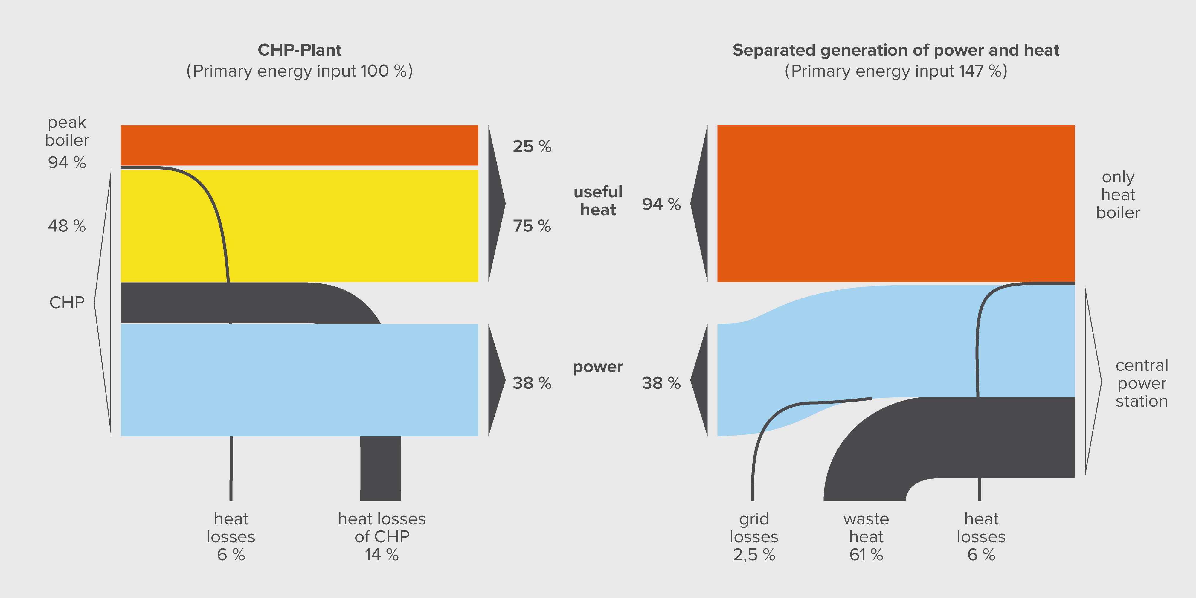
Usually, a CHP plant consists of the CHP unit and a peak load boiler. The CHP-unit covers the base heat load of the connected heat consumer (e.g. a district heating system) and the peak load boiler works only in phases of the highest heat demand. This allocation is chosen because the high investment CHP unit needs enough capacity utilisation for being cost-effective. Figure below shows the energy flow of an internal combustion engine of 300 kilowatt electric power on the left which covers 75% of the annual heat demand of the regarded consumer. The remaining part of 25% is covered by a peak load boiler. The annual power efficiency of this CHP unit is 38%. In this example, the heat loss of the CHP is 14% of its fuel input and the heat loss of the peak load boiler is 6% of its fuel input. The total primary energy demand of the complete plant (CHP-unit + peak load boiler) is set in figure 16 to be 100%.
In comparison to this, the right side of figure below shows the situation where the same heat demand and electricity generation would be covered by separated generation of power and heat. The heat would be generated by a single heat boiler, which has the same heat losses like the peak load boiler. In this case, a central power plant with a power efficiency of 39% generates the electric power (reflecting an average hard coal power plant in Germany). Grid losses of 2.5% have to be counted in order to deliver the same amount of electrical power to the site of the CHP plant. The heat losses of the central power station are very huge and equal in the example to 61% of the fuel input of the central power station. The addition of the fuel input of the heat boiler and the central power station leads to a total primary energy input of the separated generation equal to 147%.
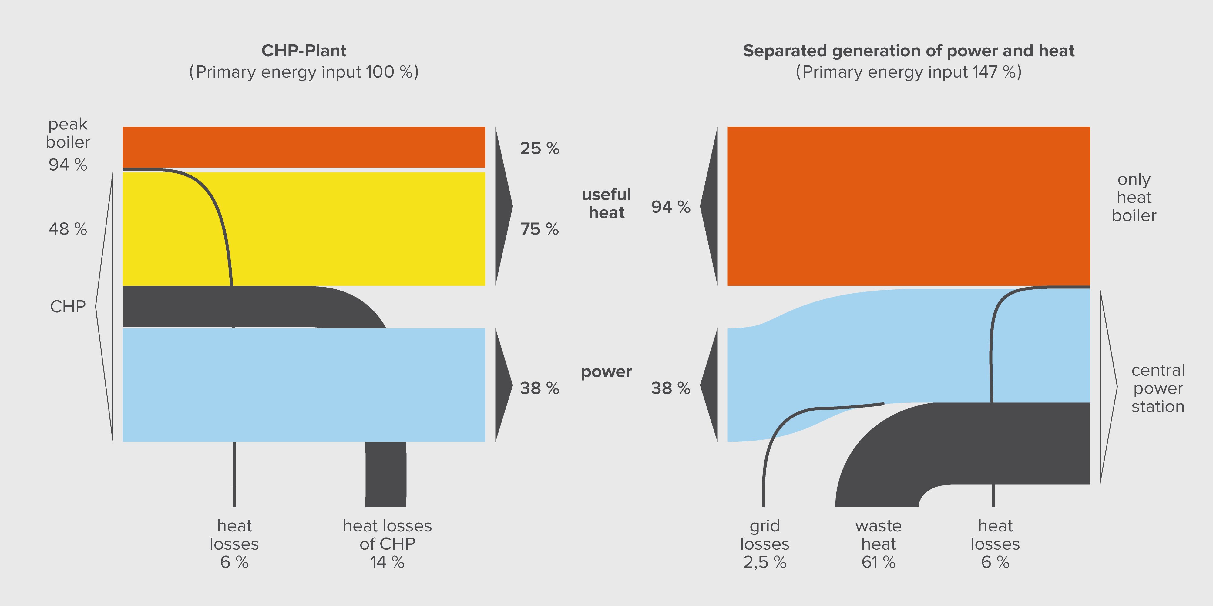
As shown in the figure above, the primary energy demand of the separated generation of power and heat in this case is 47% higher than that of the CHP-plant (CHP unit + peak load boiler). The level of primary energy saving is particularly influenced by the power efficiency of the CHP plant. One can imagine this by comparing the both flow diagrams: especially a broad electricity flow of the CHP leads to a broad flow of avoided waste heat which is strongly correlated with the primary energy demand of the separated system. This leads to the following recommendation: the ambition should be to design the CHP unit as big as possible by connecting more than one house to the plant, because large CHP units usually have higher electricity generation efficiency than smaller ones. District heating will offer the best pre-conditions to come to a high primary energy savings.
Of course, the primary energy saving is influenced by the power generation efficiency of the alternative central power station, too. If the separated generation is based on a gas-fired combined cycle with a power efficiency of 60% instead of 39%, then the energy saving effect of the CHP plant would be significantly lower. However, a realistic comparison should be based on the question, what kind of power generation capacity will be displaced by the operation of the CHP plant or which central power plant would reduce its operation capacity as a result of the CHP operation. E. g. in Germany, the power reference for a space heating generating CHP would be mainly an average hard coal-firing central power station.
Biomass plants for district heating
There are many options for biomass based heat generation within district heating schemes available. However, only few techniques are widely applied. These use
Most common is firing of wood, straw and other solid biomass and residues. The firing technique depends on the pre-treatment of the combustibles and the thermal capacity of the plant. Heat only boilers within the district heating systems use usually wood chips as a fuel. Wood chips are cheaper than compressed wood pellets, facilitate an automatic firing and offer appropriate logistics as well as good firing and emission conditions.
If the capacity of the plant exceeds 5 megawatt (thermal), in some cases it is suited as a CHP scheme. For low loads, the CHP bases on organic rankine cycles (ORC) and for the upper range steam turbines are common. Due to the lower power capacity and the fuel properties, the electrical efficiency is significantly lower than that of natural gas and coal fired CHP-plants. Co-firing of solid biomass in bigger coalfired CHP-plants offers much higher efficiency and a better cost situation. The following table shows the cost patterns of a wood chip furnace example based on German experiences:
| Heat capacity (kW) | 600 |
|---|---|
| Fuel provided (kW) | 667 |
| Specific investment (€/kW) | 670 |
| Investment (thousand €) | 402 |
| Specific variable (€/MWh) | 2.3 |
| Fixed (€/a) | 4,500 |
| Personnel (€/a) | 1,500 |
| Efficiency | 90% |
| Rate of interest | 5% |
| Service time (years) | 20 |
| Amount of annuity (€/a) | 32.26 |
| Peak load boiler | - |
| Share of the total heat capacity | 80% |
| Heat capacity (kW) | 3,000 |
| Annual efficiency | 90% |
| Specific fix operating cost (% of investment) | 2 |
| Specific variable operating cost (€/MWh) | 1.3 |
As shown in the figure below, the prices of wood chips and pellets were rather stable in the last decade when compared to final consumer prices for heating oil and natural gas.

The main representatives of liquid biomass are plant oil from oil palm fruit or rapeseed and ethanol from cane sugar, other cereals and beets. Pre-treated plant and ethanol can be then used in engines like diesel and petrol. The electrical efficiency has the same level as that of the same sized natural gas applications. However, it is to be considered that crop raising and processing demands a lot of energy input and may also require a land-use change that can cause additional greenhouse gas emissions. Given the current heat and electricity prices, the economic feasibility of this kind of CHP is dependent from governmental subsidy schemes.
Since gasifier of solid biomass up to now are not well developed gaseous biomass mainly is equal biogas from anaerobic digester of agriculture (fed with animal manure or crops) and of wastewater treatment plants. Desulfurized and dewatered biogas can be used for example in internal combustion engines like natural gas. Because of this it offers a high electrical efficiency. The heat output is lower because the anaerobic digester needs to be heated itself.
The main representatives of liquid biomass are plant oil from oil palm fruit or rapeseed and ethanol from cane sugar, other cereals and beets. As well pre-treated plant oil as well as ethanol can be used in engines like diesel and petrol. The electrical efficiency has the same level than that the same size of natural gas applications. But it is to be regarded that crop rising and processing demands a lot of energy input. Against actual heat and electricity prices this kind of CHP is dependent from financial support or regulated elevated revenues for economic conditions.
| Energy Conversion Technology | Conversion Technology Commercialization Status | Integrated CHP Technology (Prime Mover) | Prime Mover Commercialisation Status |
|---|---|---|---|
| Anaerobic digester (from animal feeding operations or wastewater treatment facilities) | Commercial technology | Internal combustion engine | Commercial technology |
| “ | “ | Microturbine | Commercial technology |
| “ | “ | Gas turbine | Commercial technology |
| “ | “ | Fuel cell | Commercial technology |
| “ | “ | Stirling engine | Emerging |
| Energy Conversion Technology | Conversion Technology Commercialization Status | Integrated CHP Technology (Prime Mover) | Prime Mover Commercialisation Status |
|---|---|---|---|
| Fixed bed boilers (stoker) | Commercial technology – Stoker boilers have long been a standard technology for biomass as well as coal, and are offered by a number of manufacturers | Steam turbine | Commercial technology |
| Fluidized bed boilers | Commercial technology – Until recently fluidized bed boiler use has been more widespread in Europe than the United States. Fluidized bed boilers are a newer technology, but are commercially available through a number of manufactures, many of whom are European based. | “ | “ |
| Cofiring | Commercial technology – Cofiring biomass with coal has been successful in a wide range of boiler types including cyclone, stoker, pulverized coal, and bubbling and circulating fluidized bed boilers. | “ | “ |
| Modular direct combustion technology | Commercial technology – Smaller boiler systems commercially available for space heating. A small number of demonstration projects in CHP configuration. | 1. Small steam turbine 2. Organic Rakine cycle 3. “Entropic” cycle 4. Hot |
1. Commercial technology 2. Emerging technology (Some “Commercial products available”) 3. Research and Development 4. Research and Development |
Geothermal plants for district heating
The geothermal energy of the Earth's crust originates from the original formation of the planet (20%) and from radioactive decay of the minerals (80%) [http://en.wikipedia.org/wiki/ Geothermal_energy]. The temperature increases under the normal conditions by 3°C per 100 m depth. In areas near tectonic plate boundaries, the temperature increase is higher. Drilling and exploration for deep resources is very expensive. There are three types of plants:
In Germany, there are currently following plants in operation:
Unfortunately, the drilling costs are rather uncertain. Due to this, new projects are dependent on rather high subsidies. Apart of this, there is a risk of damaging buildings. This stems from the fact, that the drilling can influence the hydraulic interaction between ground layers (examples in Basel (Switzerland) and Landau (Germany). More positive experiences were gained in countries with volcanic hot water wells like the USA and Iceland.
Large-scale and seasonal heat storage
Seasonal thermal storage can shift surplus heat e.g. of CHP or solar thermal systems from summer to winter and vice versa free cold from winter to summer. Thus they could become a future key element for the large scale integration of renewable and CHP technologies into local heat or cold networks.
| Artificial storage tanks | Artificial storage tanks | Natural storage media | Natural storage media |
|---|---|---|---|
| Large hot water storage tanks (elevated or soil-integrated tanks) | Gravel-water composite storage | Ground-coupled heat exchanger (geological stratum) | Aquifer storage (water saturated geological formations) |
Efficient long-time heat storage for weeks or months requires low storage leaks. Due to the disadvan-tageous surface-to-volume ratio, small heat storage tanks are unsuited for this purpose. Since mid of the 1990's different concepts of large-scale artificial or natural seasonal storages have been tested. For example in the city of Munich (quarter „Am Ackermannbogen“) a 5700 m3 subsurface hot water tank, made of steel and concrete, is connected to a 2,760 m2 solar collector field (BINE, 2011). In Crailsheim / Germany the surplus heat of a 7,410 m2 solar field is stored in a 39,000 m3 ground reservoir, loaded via 55 m long geothermal probes. Natural aquifer thermal energy storages allow the storing of great amounts of heat and / or cold over a long period with acceptable thermal losses and costs. Typical applications are the block supply / local heating of large residential or commercial buildings or areas, often heated (or cooled) by heat pumps or CHP systems and supported by large fields of solar thermal collectors. E.g. in the Netherlands more than 700 Aquifer storage projects in sandy underground have been developed (Snijders, 2008).
| City | Collector area [m2] | Storage volume [m3] | Storage type |
|---|---|---|---|
| Friedrichshafen | 4,050 | 12,000 | Hot water |
| Neckarsulm | 5,670 | 63,360 | Ground heat exchanger |
| Rostock | 980 | 20,000 | Aquifer |
| Crailsheim | 5,714 (status: January 2010) | 39,000 | Ground heat exchanger |
| Hamburg | 3,000 | 4,500 | Hot water |
| Hannover | 1,350 | 2,750 | Hot water |
| Steinfurt | 510 | 1,500 | Gravel / water |
The analysis of existing solar-thermal systems with local heating shows, that by means of seasonal storage more than 50% of the housing estates’ total heat requirement can be covered by solar energy (BINE, 2005). By using Aquifer storages 20-30% savings on primary energy consumption for heat production and 60-80% savings on electricity consumption for cold production have been realised in Dutch projects (Snijders, 2008).
Pilot project seasonal aquifer storage in Berlin: “Energy concept Spreebogen“ (BINE 2003):
In the Berlin Reichstag building, the seat of the German parliament, an innovative energy supply concept with heat and cold storage in two natural aquifer layers has been realized. In the summer the surplus heat of a 3.2 MWel plant oil CHP unit as well as heat out of cooling processes and solar thermal collectors is loaded into a ca. 300 m deep thermal aquifer storage (see figure below).
")
| Summer (loading) | average delivery temperature: | 20°C |
|---|---|---|
| - | injection temperature: | 70°C |
| - | stored heat: | 2,650 MWh/a |
| Winter (unloading) | delivery temperature: | 65 – 30°C |
| - | extracted heat: | 2,050 MWh/a |
| Balance | Electricity demand for pumping : | 280 MWh |
| - | Ratio of utilized to stored heat: | 77% |
In winter approximately 70-90% of the stored heat can be regained and used for peak load coverage. In the cold storage at about 50 m depth the winter’s cold, won through free cooling, is stored which can be used for high temperature cooling in summer (flow / return temperature: 16 / 19 °C). Additional low temperature refrigeration (6 / 12 °C) can be provided by CHP waste heat supplied absorption chillers. The main advantage of aquifer storages is the low investment or development costs. They are (without VAT but including planning) approximately in a range of EUR 25 per cubic meter storage capacity and thus significantly lower than those of alternative storage technologies such as concrete storages (120 to 450 EUR/m3), steel tanks (600 to 3,000 EUR/m3) or glass-fibre reinforced plastic (GRP) storages (125 to 430 EUR/m3). Starting from a certain size (ca. 100,000 m3) the storage loss becomes, due to a favourable volume-to-surface ratio, acceptable small, although the heat storage is uninsulated. Prerequisite for the use of a natural aquifer storage are, however, appropriate hydrogeological local conditions. Similar innovative projects for long-term storage of heat have been realized in Rostock-Brinckmannshöhe (aquifer storage for solar thermal heat, BINE, 2007), in Neubrandenburg (heat storage of a combined-cycle plant into thermal water containing layers, BINE, 2007), in Munich (solar local heating project “Ackermannbogen”, BINE, 2011) and Crailsheim (solar thermal local heating project “Hirtenwiese”, BINE, 2012).
Vacuum storage tanks
A new approach for minimizing thermal storage losses in spite of compact form is the vacuum insulation. Similar to a vacuum bottle these steel tanks are double-walled and evacuated in the space be-tween. The space is filled with packing materials of special thermo-dynamic properties to absorb the mechanical forces caused by the vacuum. The storage losses of 2 Watt per Kelvin (or 0.2 °C per day at a temperature difference of 90 °C) for a 16 m3 vacuum tank are about 80% lower than those of conventional tanks insulated with mineral wool. Thus this new approach allows also seasonal storage with ac-ceptable thermal losses even for smaller storage volumes. First pilot projects with 11 m3, 26 m3 und 48 m3 vacuum steel tanks have been implemented in Germany (Banse, S. 2011).
Plastic medium pipes or steel medium pipes with plastic jackets are preferable. The district heating network can be divided into the main pipes and sub-distribution pipes like branches and twigs of a tree. Small district heating systems are similar to sub-distribution schemes. Usually, use of the sub-distribution (especially the “twigs”) leads to significantly higher costs per distributed kilowatt-hour heat than the main network (despite the fact that the main pipes cause higher per meter costs). The house connection pipes have the smallest diameter. Within the last two decades, a lot of new development took place with respect to the district heating technology. These lead to more cost efficiency, durability, reliability, higher comfort levels as well as less heat losses. In the following, a principal classification of district heating pipe systems in connection with a brief appraisal is given:
| According to its arrangement: | Remarks |
|---|---|
| Above ground level pipe (aerial pipe) | Declining acceptance because of aesthetic reasons |
| Duct laying | Main principle in the past, high investment |
| Buried pipes | Common |
| Indoor pipes / cellar pipes (from house to house) | Low investment, conditioned by the presence of appropriate circumstances |
| According to pressure and temperature: | Remarks |
|---|---|
| Steam network (supply temperature: 150 – 220°C) | Replacement of steam network by a hot water network in many places if other than industrial customers are connected |
| High temperature water network (> 110°C) | In many places efforts to limit the max. Temperature (< 130°C) |
| Low temperature water network (< 95°C, in some cases < 70°C, seldom < 45°C) | Several advantages, especially in low density settlements |
| Technical solutions of district heating pipe systems: | Remarks |
|---|---|
| Pre-insulated bonded pipe systems (straight or flexible pipes) | Since more than two decades state of the art, many different materials, especially for the medium pipes |
| Twin pipe system | Upcoming, lower investment, limited in the available diameter |
| Combination of steam pipe and condensate return pipe | Application should be limited to industrial consumers |
A further distinction is given due to the chosen materials of the medium pipes, the insulation material and the jacket pipe. Medium pipes are mostly made out of steel, followed by heat resistant plastic and in special cases by copper or aluminum. The characteristics and the availability of the common systems are as follows:
| Plastic jacket pipe | Steel jacket pipe | High-frequency welded steel pipes (Steel-Flex) |
|---|---|---|
| Mid-range investment needs due to pre-fabrication | Very high investment needs | Pipe system rather expensive |
| Maximum temperatures up to 130°C (higher temperatures would be possible for short time periods, but lead to insulation aging and plastic jacket stress) | High stability → tolerates high temperatures and pressures up to 400°C and 64 bar | Suitable for house entries |
| Diameter up to 1200 mm | Diameter up to 1200 mm | In DH systems with high tempera-tures and pressures (continuous operation temperature up to 120°C) |
| Laying procedure is technically mature | Highly efficient insulation concepts available | Jointing method is traditional welding |
| Most common in Western Europe | Laying procedure is technically mature | Offers high flexibility in cases where there are other pipes, grids and roots crossing the system |
Plastic medium pipe systems:
Pre-insulated bonded pipe systems are the most common. The base of the pipe is a poly-urethane foam (PUR) insulation around the medium pipe. The outside jacket pipe together with the medium pipe then offers a long-term stability against the stress stemming from the changing temperatures.
As a new development, an aluminum membrane between the outer casing and the insulation material has been added. This makes the pipe system diffusion-tight. It prevents the insulation gases from leaking through the plastic casing and being replaced by air with inferior insulation properties. Plastic jacket pipes with steel medium pipes represent the most common system. They offer a high durability with moderate costs per meter and resist temperatures up to 130°C. Unfortunately, plastic medium pipes are frequently connected with damages like water losses and elevated heat losses. This stems from the fact that the modular design principles for interconnecting the plastic medium pipe systems seem to be rather easy which in many cases leads to installation by an unskilled worker. Assuming professional installation, plastic medium pipe systems can offer service life comparable to steel medium pipes at a lower cost.
Steel jacket pipes are chosen under special conditions like high insulation demand, high temperature stress or special laying conditions. Steel-flex systems facilitate the laying in cases where there are other pipes, grids, roots or other barriers in the track of the system. Furthermore, thanks to their temperature resistance, they can be used in combination with usual plastic jacket pipes.
Especially in Scandinavian countries, use of systems with two pipes within one jacket pipe – so-called twin pipes – is becoming more and more common. The level of heat exchange between the supply and return pipe in comparison with single pipe systems is acceptable if a higher insulation class is chosen.
The joints, branches and other fittings
For every pre-fabricated district heating pipe system, special joints, branches and other fittings are available. These are designed to minimize the installation costs. Welded joints are common for steel medium pipes. In case of plastic medium pipe systems, 3 different kinds of joint system casing are available:
As a link between the district heating and the house heating installation, a house substation allows heat metering, controls the pressure and temperature of the house internal loop, includes cut-off devices and offers in many cases the preparation of hot domestic water. For the connection of house installations, two types can be distinguished: the direct application of district heating water or steam and the indirect scheme consisting of a heat exchanger which divides the district heating water loop from the heating loop of the single house. In case of multi apartment houses, there can be substations in every apartment. For instance, substations for house groups (central substations) are common in Eastern Europe.
Indirect schemes of district heating network connection for space heating systems
In case of indirect schemes, the district heating and the radiator networks are separated from each other by means of heat exchangers. Compared with direct schemes, this solution offers the following advantages:
On the other hand, this solution requires more technological equipment - such as heat exchangers and pumps - than direct schemes and hence higher associated investment.
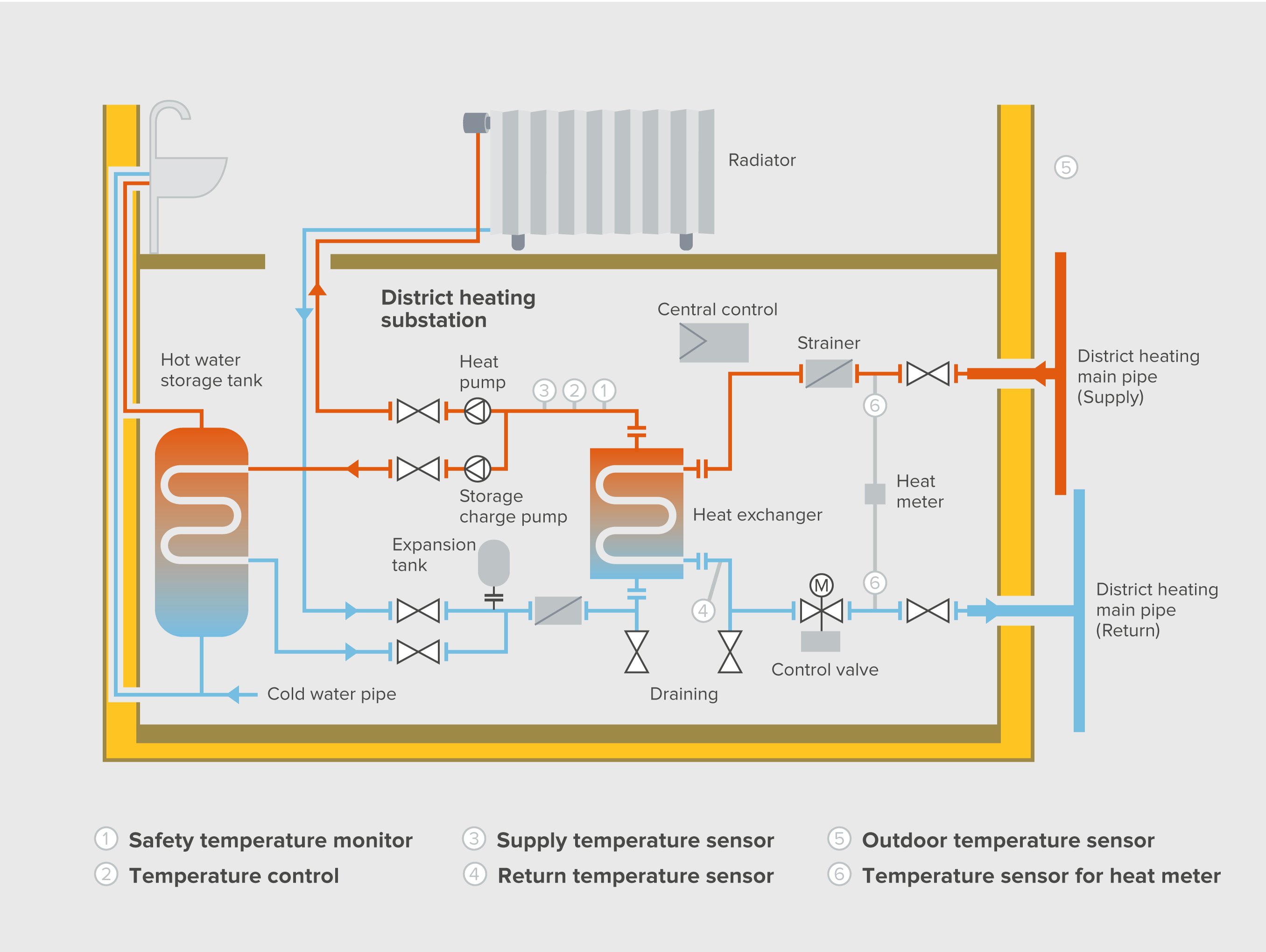
The figure above shows the principle of an indirect district heating connection (right hand side) in combination with a closed hot domestic water generation (see the heat storage tank on the left hand side) which can be classified as BAT of Germany. Highly energy-efficient circulators should be used in house substations. Particularly the new generation with permanent magnet motors (EU energy label class A) can save up to 80 % of electricity and be very cost-effective compared to conventional technology.
Direct schemes of district heating network connection for space heating systems
Within the direct schemes, the district heating and the radiators are directly connected (as shown in the figure below) meaning that district heating water flows through every heating device. In Western Europe, this scheme is carried out in some cases of supply temperatures under 70°C and in cases of new buildings. This solution is also still very common in the former Eastern Bloc countries (Russia, Poland, China etc.).
The advantages are:
Nevertheless, the disadvantages seem to outweigh these:
At present, even the direct schemes functioning with low supply temperatures seem to be less preferred, possibly due to the higher insurance rates.

Principles of domestic hot water generation
Domestic hot water generation in district heating can be classified as closed or as an open scheme. The latter is very uncommon in Western Europe. An open scheme means that the district heating water flows directly to the taps (see figure below). Of course, this leads to minimal investment on the consumer side. On the other hand, this solution is associated with significant district heating water treatment costs due to its requirements on the makeup water quantity when compared to closed system. Other disadvantages are:
Furthermore, it also causes high corrosion of pipes and of other devices, which in turn reduces the service time of the whole district heating system and increases the cost.

There are several types of the closed schemes:
Continuous-flow water heaters, which provide hot water directly from a heat exchanger (see figure below), can be characterized as follows:
Domestic hot water storage tanks with external heating unit (figure 15 b) can cause undesired high return temperatures. However, in case of storage tanks with charging system (figure 15 c) which are load-ed by an internal heat exchanger, this disadvantage can be avoided.

Furthermore, these three principles of closed schemes can be further divided into direct and indirect domestic hot water heating. Direct domestic hot water heating describes a concept where the heat exchanger, which heats cold water directly, is circulated by district heating water. This leads to lower investment than indirect schemes and enables also a lower return temperature. However, the hazard of heat exchanger leakage which can go unnoticed for a long time and deteriorate the quality of the district heating water and of the domestic hot water can be classified as a serious disadvantage. Indirect domestic hot water heating includes a further heat exchanger which transfers district heat to a medium pump-driven heating circuit. In contrast to open schemes, this solution is also called a closed system.
Optimal pipe systems
General reconstructions of the existing district heating network and new district heating projects should be used to optimise technical system towards cost efficiency and sustainability
Low temperatures
In case of new district heating projects potentials for low supply temperatures should be used. Low supply pipe temperatures
However, given the health hazards caused by legionella bacteria in domestic hot water generation systems, the minimal supply temperature should not be lower than 60°C. The return temperature behind the heat exchanger of the hot domestic water generator should be at least 55°C. Nevertheless, due to the higher capacity utilisation of the district heat generator and often improved energy balance, domestic hot water should be generated by district heating.
A pre-condition for low supply temperatures implies keeping the return temperature of the district heating system as low as possible. The return temperature is influenced by the size of the connected radiators and the heating control systems in the houses. Furthermore, a low return temperature increases the heat transport capacity of the district heating network and offers the potential to reduce pipe diameter and / or pump capacity. Additionally, in many cases it improves the efficiency of the heat generators and reduces heat losses of the network.
The return temperatures are particularly influenced by the size of the radiators. The installation of large radiators, which allow a higher cooling of the supply temperature and therefore need a lower flow rate to cover the same heat load than small radiators could be supported by an incentive which offers customer with a high difference of supply and return temperature a lower heat price. Furthermore, a lower return temperature will be achieved if heat consumers, who need only low supply temperatures (applied for drying, swimming pools, floor heater etc.), are connected to the return pipe instead to the supply pipe. This could be stimulated with the help of a special price system.
Usually new district heating system should be applied only on the typical urban settlements. The overall yearly heat demand of all connected buildings should exceed about 1,000 kWh/m pipe length (without counting the connection pipes length to the houses). Lower heat demand per meter is acceptable in case of new buildings and settlements as these provide further opportunities for cost reduction.
Refurbishments on the other hand present a different set of challenges albeit not without having incentives to make the transition from older or other forms of heat supply to district heating. The following sections provide insights into installing new district heating systems and refurbishment of existing ones.
makes energy efficiency in buildings and appliances transparent. For investors, policy-makers and actors involved in implementation and consultancy. Learn more ...


 Buildings Guide
  Policy Guide
  Appliances Guide
  India
India South Africa