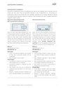
DX (Direct Expansion) Air-Conditioners (AC) use ‘refrigerant vapour compression/expansion cycle’ to produce cooling (in other terms, to remove heat from the space). The heat is removed from the space through natural or forced convection by an ‘evaporator’ unit that is usually located within the space (packaged units however, use ducts and big fans). The heat removed from the space is rejected to the outside atmosphere through a ‘condenser’. Various configurations of DX units are in use such as window AC, split AC, heat pumps, Variable Refrigerant Volume/Flow (VRV/VRF) AC and also packaged ducted units. The following diagram (see diagram below) explains the basics of a vapour compression refrigeration cycle in a typical window air conditioner. Air conditioners using the vapour-compression cycle typically consist of the following key components: 1. compressor 2. condenser 3. expansion device 4. evaporator. For more information on the working details of a DX air-conditioner check the technical description given below.

Depending on the size of the system and requirement the refrigerant is either circulated on its own because of the pressure variation (domestic RAC units) or it is assisted by the use of pumps in large-scale systems (some Variable Refrigerant Volume systems and chillers).
The high-pressure side is generally referred as high side or demand side (where work is done to increase the temperature and pressure of the liquid) and the low-pressure side is referred as low side or supply side (where cooling occurs and is distributed). The figure below shows a graphical representation of the refrigeration cycle on a pressure-enthalpy graph.

Most DX air conditioners find application in residential buildings, small shops, offices, small super markets, data centers, etc. They can act both as local air conditioners used to cool individual spaces and also as central units to cool multiple spaces.
Local/room DX air conditioners
Local DX air conditioners (room air conditioners) are used to cool individual rooms. Typically, one unit servers per one room. They are generally obtained in two configurations i.e., non-ducted unitary/window units and non-ducted split units. Ventilation generally occurs through infiltration or forced air changes through opening of doors and windows. They sometimes also have a separate mechanical ventilation system in place.
|
More information on local/room DX Air-Conditioners |
|
Central DX air conditioners
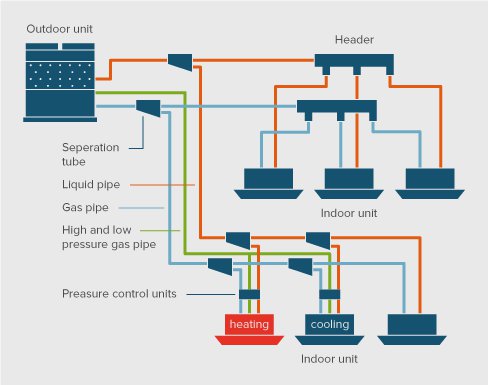
Central DX systems are interconnected by refrigerant pipe work with a separate indoor and outdoor unit and are called multi-split units and are increasingly used to provide flexible and modular cooling (and heating when the systems are reversible) systems for residential and commercial buildings. E.g., multi split/VRV/VRF units, packaged ducted units are used to cool multiple rooms and large dwellings. Ducted split units may have a separate ventilation unit whereas ducted central systems (packaged central) include a ventilation system.
|
More information on central DX Air-Conditioners |
|
Different types of DX air conditioners have different approaches to space cooling depending on the location of the equipment; space needed, heat rejection mechanism to the outside and ranges of cost to the consumer. These factors have a significant impact on the efficiency levels that can be achieved for each type. Various types of DX units are used throughout the world, although details of the design, capacity and operating temperatures vary according to climate and in particular according to humidity.
Generally speaking, the greater the temperature difference between the cold end (evaporator) and the hot end (condenser) of the air-conditioning system (also called the load), the lesser is its working efficiency. The system has to work harder and less efficiently as the outside temperature rises or as the space setpoint temperature is lowered. This is why an identical product will perform with different efficiency depending upon the ambient and operating conditions at various locations; for example, in hot-humid conditions compared to temperate conditions. Products are generally optimised, or have specific features, to suit a regional climate conditions. The most energy-efficient vapour compression units today remove six units of heat per one unit of electricity (at AHRI standard rating conditions for full load efficiency).
Efficiency of the DX air conditioners is often expressed in terms of nominal EER or COP. Nominal EER however, does not provide a clear picture of actual performance. This is because the efficiency of an air conditioner varies as the load on the system varies. Every DX compressor has it’s own load performance curves. The figure below shows a comparison of typical on/off compressor to that of an inverter driven compressor. Part load performance curve indicates the efficiency (index of efficiency relative to COP at 100% load) with which the system operates at a given part load value (as a % of the full load).

The world’s most efficient residential air conditioners have nominal COP of approaching or even exceeding 6, with a theoretical maximum of around 6.5 today (CLASP, 2011). This reveals significant scope for improvement compared to typical DX AC units with sales weighted averages ranging between 3 and 3.5 for most countries (CLASP, 2011). For example, the best European products achieve a COP of 5.63 (Michel et al., 2011) for units smaller than a capacity of 4 kW and a COP of 4.52 for units over a capacity of 4 kW. Multi splits achieve a COP of 4.97 but mobile units achieve a COP of only 3.22 (in Europe). For a comparison between price and efficiency of various types of systems see the following table.
| Type | Non-ducted Split/multi-split | Ducted central systems | Unitary/Window AC | Single duct / double duct and mobile |
|---|---|---|---|---|
| COP (conventional) | 3.5 | 3.5 | 2.5 | - |
| COP (BAT) | 6 | 6 | 3.5 | 5.5 |
| Price (€/kW) conventional | 195 | 195 | 140 | 180 |
| Price (€/kW) BAT | 265 | 265 | 250 | 320 |
| Typical capacity (kW) | 30 | 30 | 10 | 7 |
| Simple payback (in years) (minimum 500 hr/yr at full load conditions and at EUR 0.15/kWh) | 8 | 8 | - | - |
Each of the key components of air conditioners have technology solutions that can significantly improve the efficiency compared to average DX units. In some markets most, or all of these, are necessary features to achieve the local regulatory minimum standards (e.g. in Japan) and are typically seen in high efficiency products in many markets. Each technology is summarised below and in the table below along with the indicative energy savings they can achieve if applied on their own to a basic low efficiency unit. Note that the different technologies interact and savings overlap, so savings from each cannot be added together to estimate overall potential.
The most important manufacturer energy efficiency improvements that can be made to basic low efficiency units are (in approximately descending order of importance):
| S.No | Measure | Comments | Indicative annual energy savings range (%) |
|---|---|---|---|
| 1 | Compressor | Inverter control, matching speed to cooling demand | 30% (up to 50% in some applications) |
| 1a | Compressor | DC drive motor; better compressor | Up to 15% |
| 2 | Dedicated dehumidifier | Use dedicated dehumidifier or two stage compressors | 20-40% depending upon the humidity levels |
| 3 | Improved heat exchangers | Larger/improved condenser and evaporator | Up to 25% |
| 4 | Improved expansion valve | Electronically controlled | 9% |
| 4a | Improved expansion valve | Thermostatically controlled | 5% |
| 5 | Variable speed inverter driven fans | For evaporator and condenser fans | 4% |
| 6 | Reduced standby | Electronics: Savings are higher in temperate climates (less usage) and for smaller units | 3% for aver-age sys-tems |
| 6a | Reduced standby | Crank case heater: Only applicable in 10% of units for cold weather usage (often reversible units). Savings higher % for temperate cli-mates (less usage) | Some units: Up to 50% in cold weather climates |
Energy savings in the range of 30% to 50% can be made by matching the capacity of operation of the compressor to the required cooling load using a variable speed inverter control enabled compressor. Air conditioners with VRV/VRF compressors are usually cost effective with a payback period of about 3 – 6 years in hot &dry and hot & humid climates.
Technology description
Inverter driven compressors a.k.a. Variable Refrigerant Flow/Variable Refrigerant Volume (VRF/VRV) compressors work on the principle of “vapour compression cycle”. The key improvement is that they can operate at a full speed at the start of operation to achieve the set temperature in a short time and then shift to low-speed, partial capacity operation. Thereafter, by operating at a flexible speed matched to the cooling requirement at that moment and comfortable room temperatures can be maintained with much reduced power consumption from avoiding on-off cycling. Typical efficiency of VRF units is about EER of 4.5 and the best available technologies have efficiency of more than EER of 6. Most VRF models can be used in reverse mode as heating units during winter months and require less maintenance.
Due to several contributory factors the simpler alternative of turning the compressor on and off to reduce capacity suffers an efficiency penalty of around 10% compared to full load efficiency when the cooling load is at 50% of full load; the penalty is 25% at 25% load (numbers typical for a 4 kW RAC). But importantly, running the compressor at lower speed actually increases the efficiency with which the lower cooling load is achieved over most of the loading range, with a maximum of around 140% of full-load efficiency at just under half of full load (see figure below).
Usage
VRV/VRF systems can have from 1 to upwards of 10-25 indoor units of varying capacity (for each outdoor unit and multiplies as blocks thereof for higher capacities) that are controlled in zones with a common communications network. Different type of indoor units can be attached to an outdoor unit. Typical indoor units include Fan Coil units (FCUs), Ducted units etc. VRV/VRF systems are typically used to serve multi zone buildings such as multifamily residential buildings, high-rise residential buildings, hotels, and offices etc., which need air conditioning most of the time. Typical size of the system varies from 20 kW – 490 kW. Inverter control also improves user comfort, as the set point temperature is maintained more accurately in many applications compared to a fixed speed system. Inverter drives and improvements to compressor efficiency are applicable to all types of DX air conditioners and in all climate zones. Proportionately higher efficiency gains can be made through inverter driven compres-sors for smaller single duct units, compared with split units.
VRV/VRF units are higher in purchase and installation cost compared to window units. This higher cost margin will soon be overcome due to the increasing demand for efficient systems with VRV/VRF technology and economies of scale. In addition, the requirement of a separate mechanical ventilation system is required to meet tight ventilation code requirements where applicable. Local ventilation equipment with inbuilt heat recovery unit can be easily integrated with VRF units for higher benefits.
Savings
The most energy-efficient split air conditioners
with variable speed drive compressors and fans and COP of up to 6 will
save up to 50 % of energy compared to constant speed compressor split
units and even more compared to window and portable units (ARMINES,
2008).
Market scenario
The proportion of variable speed (and
multi-speed) compressors in most markets has grown significantly since
2000. Inverters accounted for less than 5% of EU sales in 2002 but
around 50% by 2009 with even faster growth in Australia to around 55% by
2008. Inverter drives dominate the Japanese and Korean markets, and
accounted for at least 10% of the Chinese RAC market in (IEA 4E, 2011).
In hot humid climates air conditioning systems perform a dual task of cooling (sensible load) and also dehumidification (latent load), which occurs as a by-product of cooling. This increases the unnecessary latent load on the system. Using dedicated dehumidification system or two stage cooling system uses less energy to dehumidify than the conventional air conditioning system primarily intended for cooling. This minimizes unwanted latent load on the system and savings in the range of 20-40% can be made.
Technology description
In residential air conditioners dehumidification occurs as a by-product of cooling. When indoor air comes into contact with the evaporator coil moisture from the air condenses on the coil making the indoor air dry. Lowering the humidity of a room can make higher temperatures more comfortable for occupants and avoid damage from humidity. Allowing higher internal temperatures can in turn lower the overall cooling requirements, assuming humidity control is done efficiently.
In hot humid conditions if humidity is not removed efficiently, cooling can create condensation on cool interior surfaces and create cold, clammy conditions. Occupants will then often compensate for this clamminess by setting the temperature much lower than would be the case if the space were drier, wasting energy and causing even more condensation and discomfort (Baechler & Love, 2004). Similarly in hot dry conditions excessive cooling causes the air to be drier than the required level for comfort. This problem mainly occurs because as explained above, dehumidification in residential air conditioners is just a by-product of cooling and most RACs are not explicitly designed for tackling both cooling and dehumidification. However, recent commercial domestic air conditioning products are being designed to tackle both at the same time.
Cooling and dehumidification is most effectively done using a lower temperature in the cooling unit than would be required for normal cooling of air. This is typically 6 to 7 °C, significantly lower than the typical operating temperature used for cooling which is around 16 to 17 °C. This significantly increases the temperature differential between the cooling and heating side and therefore reduces efficiency. Efficient designs for hot-humid climates will use a special purpose, smaller cooling unit to achieve dehumidification. This unit will only run when necessary to keep humidity in certain bounds, whilst the main air cooler continues to operate at the higher, more efficient, operating temperature (Shirney III, Henderson, Jr., & Raustad, 2006). There are also designs that use two/multi-stage compressors that take both internal temperature and relative humidify into consideration instead of operating only to maintain sensitive temperature and thus excessively dehumidifying the space. An alternative is to combine the air conditioning unit with a desiccant dehumidification system to improve efficiency. However, desiccant dehumidification is more popular and feasible in central systems rather than in residential buildings.
Market scenario
Commercial air conditioning with advanced controls and technologies like dual compressor or dual/multi- stage compressors for optimal maintenance of space temperature and humidity at highest levels of energy efficiency are now available. They are increasingly becoming popular in Coastal American and Asian markets with high humidity climate zones. Since the technology is relatively new and it is a continued technological development over conventional vapour compression cooling machines, market data is not explicitly available. However, sales of these advanced units in emerging markets gives an estimate of the market intrusion of these systems.
Savings
Simulation studies conducted by Aprilaire demonstrates energy savings due to the use of an air conditioning and dehumidification system to conventional cooling strategies. The dedicated system has a temperature set point of 25.5 °C and a humidity set point of 25 °C. This system is compared with three conventional strategies and it has been concluded that significant energy savings can be incurred with increased thermal comfort in each case. The study has been carried out to resemble an air tight, high energy efficient house in hot, humid climate of Florida (Aprilaire, 2009).
| Strategy | Dedicated dehumidification strategy | Conventional strategy | Comparison | Operation Time, hours | Time > 60% RH, hours | % Energy savings |
|---|---|---|---|---|---|---|
| Conventional Strategy 1 | Set-point temperature of 25.5 °C and RH 59% throughout the year | Set-point temperature of 24 °C throughout the year | Conventional strategy 1 | 1,911 | 1,641 | - |
| - | - | - | Dedicated dehumidification | 1279(AC) 258(DH) | 0 | 18 |
| Conventional Strategy 2 | Set-point temperature of 25.5 °C and RH 59% throughout the year | Over cooling with a set-point temperature of 22°C throughout the year | Conventional strategy 2 | 2,757 | 280 | - |
| - | - | - | Dedicated dehumidification | 1279(AC) 258(DH) | 0 | 44 |
| Conventional strategy 3 | Set points of 25.5 °C when occupied (November through April), and 29.5 °C when unoccupied (May through October) and 59% RH year-round. | Set-point temperature of 24 °C throughout the year | Conventional strategy 3 | 1,245 | - | - |
| - | - | - | Dedicated dehumidification | 414(AC) 354(DH) | 0 | 43 |
There are many ways to improve the efficiency of heat exchangers. Microchannel flat plate heat exchangers provide good efficiency. By simply making common heat exchangers larger is also highly effective. Efficiency improvements can be costly at around 60% higher unit cost for a 25% higher efficiency (for a 7 kW split system) (ARMINES et al., 2009b). Larger heat exchangers are not a practical option for some types of air conditioner such as window and portable units. However, in these cases careful design and the use of the most efficient heat exchangers can make useful savings for all types of unit.
Technical description
In their simplest form, both the indoor and outdoor heat exchangers
usually consist of a grid of narrow pipe work through which air is blown
with a fan; the refrigerant is pumped through the pipe work. There are
many possible design enhancements including size of the heat exchanger,
fins on the pipes, texturing of internal and external surfaces,
features to enhance air and fluid flow, density and arrangement of pipe
work and many more.
However, the single most influential factor is the available surface area for heat exchange. Larger surface area generally means higher efficiency, because more heat can be transferred at a lower temperature difference between the air and the refrigerant. This reduces the temperature lift for the air conditioner and improves efficiency (each degree Celsius reduction in temperature typically improves efficiency by 2% to 3%). The design process inevitably results in complex trade-offs between efficiency, unit cost, physical size of the unit, noise from air flow and other issues. Different manufacturers approach this in different ways to achieve a wide range of efficiency, and cost, outcomes.
Some types of unit are particularly constrained on size and price such as window and portable units, which will inevitably limit their scope for high efficiency. Splits have more scope for larger heat exchangers and better airflow, which is reflected in their better efficiency. Improved heat exchangers are applicable to all climate zones and regions. However, raising the temperature of the cooling elements to achieve better efficiency results in a unit that is less able to quickly remove humidity from the air. This is a drawback especially in hot- humid climates. To optimise performance some units therefore, have additional lower temperature coils for humidity control that are used only when required, with the temperature cooling done by the main heat exchanger(s).
Savings potential
A cooling only split RAC (7 kW) (ARMINES et al., 2009b) that achieved a 25% improvement in efficiency from improving heat exchangers would increase the price by 60%. For the same product, a 14% efficiency increase adds 23% to the purchase cost. Efficiency gains through heat exchanger design are less for single duct units than split units, with a maximum of around 16%. The savings from larger heat exchangers would accumulate consistently over the cooling season due to lower temperature lifts, being particularly beneficial at times of high ambient temperature. Efficiency benefits could not be fully exploited if humidity control is a major requirement because condensing water from the air requires a lower tem-perature on the heat exchanger surface.
Improved heat exchanger technology is prevalent in those nations with MEPS for which split type air conditioners dominate the market. It is less exploited in purchase-cost focused and space constrained markets, as well as markets dominated by small packaged unitary air conditioners (window units).
The expansion valve controls the flow of refrigerant in the system cycle. Two levels of improvement are possible over the basic option of a short length of small bore tubing serving as a ‘valve’. A thermostatically controlled valve can save 5% of energy; an electronically controlled valve can save 9% (ARMINES et al., 2009b).
Description of the technology
The expansion valve regulates the flow of refrigerant through the air conditioner pipe work, and in particular to the evaporator (cooling unit). At its simplest and most inefficient, an expansion valve is simply a short length of small bore tubing. This results in sub optimal flow rates as well as losses when the compressor stops, as refrigerant will simply flow backwards through the tube. This is common option in basic and/or cheap air-conditioners.
Better control and efficiency is achieved through a thermostatic expansion valve which can vary the flow according to temperatures in the system. A more sophisticated electronic expansion valve, with its intelligent controls, can achieve higher savings. BAT products will certainly make use of electronic ex-pansion valves. This technology is applicable to all types of air conditioner, in all climate zones and regions.
Savings potential
For a 7 kW split RAC system, a thermostatic valve could save 5% on energy consumption with a price increase of 1.5% (ARMINES et al., 2009b) while savings of 9% can be achieved by the more sophisticated electronic expansion valve at a cost increase of 3.5%. Savings and prices for adding improved expansion valves to large central air conditioner plant are more variable but are of the same order of magnitude.
Efficiency in air conditioning systems is best when the fans in the evaporators and condensers are inverter driven so that cooling capacity is matched with cooling demand, hand-in-hand with an inverter driven compressor. For non-ducted systems, e.g., a 7 kW split unit these improved fans might cost 7% more and can save upto 4% of energy. Ducted systems have a higher proportion of total energy used for fans and air movement and so savings are greater for these from improved fans and fan motors.
Description of the technology
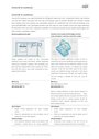
Fans and pumps are critical energy consuming components of HVAC systems. Fans are used for both ventilation and circulating conditioned air and and pumps are used to circulate chilled water. Cooling load on the HVAC systems varies depending on the usage and weather. Heat, and also sometimes humidity, is removed from ambient air when it is blown across the cooling coils (indoor heat exchanger) of the air conditioner. How quickly and efficiently this heat transfer happens is intrinsically linked to the speed of airflow and how the air flows through the heat exchanger coils. Both fans and pumps need not necessarily operate in full load conditions all the time.
VSD attached motors (see figure below) use as much power necessary to meet the load and enables the motor to increase or decrease the speed.

The fan and pumps, used mainly for air-conditioning and heating, are most of the time centrifugal and are characterized by a variable power consumption according to the cube of speed (see figure below). Variable speed drives are fixed on to the motors of pumps and fans and consist of intelligent circuit to control the speed of the motor. It regulates the operation of the motor as per the demand and saves significant amount of energy.
A key efficiency improvement is matching capacity (via air flow rate) to cooling demand using inverter driven (variable speed) fans/pumps. When less capacity is needed, very substantial energy savings can be made by reducing the fan speed. Fan efficiency can be measured in terms of cubic metres of air per minute per watt of fan power. E.g. a pump needs only 20% of power to run at 60% speed while it needs 50% of power to run at 80% speed.
For example, a 20% reduction in rotational speed yields nearly 50% reduction in energy consumption. For the same pressure and volume, a larger diameter fan is much more efficient than a smaller one - a 10% larger diameter impeller leads to a 41% energy saving. Direct drive between motor and fan avoids the losses associated with belt or other drive types, but power losses do occur in variable speed drive units. Permanent magnet motors offer the most efficient solution.

Savings potential
Matching the cooling capacity with the cooling demand can make significant efficiency gains. Hand-in-hand with introducing inverter driven compressors manufacturers have introduced inverter driven fans on the indoor and outdoor heat exchangers in split/VRV units. A poor unit may only achieve a flow of 0.15 m3/min/W, whereas an average indoor fan coil might achieve a flow of 0.25 m3/min/W with a best practice level at 0.5 m3/min/W. Air flows through the outdoor coil are higher with an average unit at 0.33 m3/min/W and best practice between 0.8 m3/min/W and in excess of 1 m3/min/W. These figures are indicative only and highly dependent upon the design approach taken to optimise fan and heat exchanger design. Electronic control of fans provides scope to optimise cooling capacity and efficiency dependent upon ambient conditions and control settings. Inverter driven fans are a very suitable efficiency option for split units. Inverter driven fans are applicable to all climate zones and regions.
Adding inverter driven fans to both indoor and outdoor components of a 7 kW split unit would add some 7% to the price, but achieve an additional 4% savings over and above that achievable through an inverter driven compressor (ARMINES et al., 2009b). Using two smaller fans instead of a single fan in a single duct unit offers a saving of around 11% compared to an average unit, but adds some 8% to the purchase price.
Standby consumption of controls etc. can account for as much as 20% of annual consumption in temperate climates, but typically less than 10% for split and larger units. Cost-effective measures could reduce these parasitic losses by 80%. Of even more concern are the parasitic losses associated with oil heaters in some 10% of products. In temperate climates these heaters can consume more energy in a year than is used for cooling, and often equate to the consumption of a household refrigerator. Technical improvements (part and parcel with other efficiency measures) can avoid the need for such heaters altogether for most products (NACEE, 2004).
Description of the technology
There are two ways in which an air conditioner can draw power when it is switched to a standby mode and not actively cooling:
Savings potential
A best practice standby consumption of less than 1 W could save around 3% to 4% per year. For products which have an oil heater the overall system energy consumption (for 3 to 7 kW splits that are constantly heating) could be halved in a temperate climate by eliminating the heater. The percentage reduction would be less in hotter climates, as overall consumption is higher. Savings for a 3 kW split unit would be a similar proportion. Savings through reduced control standby and crankcase heaters are
applicable to all product types and climate zones and regions.
Proportionate savings from eliminating the crankcase heater could vary
significantly, being highest in cold regions if any temperature related
control was present. Note that only around 10% of products have these
heaters.
makes energy efficiency in buildings and appliances transparent. For investors, policy-makers and actors involved in implementation and consultancy. Learn more ...


 Buildings Guide
  Policy Guide
  Appliances Guide
  India
India South Africa