An electric chiller is a machine producing chilled water for air conditioning purposes. Chilled water is typically procured at 4 - 6 °C. It works on the principle of vapour-compression refrigeration cycle. Common refrigerants used in chillers are R 22, R 12, R 123, R 134A Ammonia. Commercially available chillers vary in capacity from 50 kW to 5 MW or even more in specialized conditions. Typical life expectancy of electrical chillers is approximately 25-30 years.
An electric chiller works on the principle of vapour compression cycle except that the equipment is more robust with a slightly different arrangement from that of a DX Air-Conditioner. Typically expansion valve, evaporator and compressor are housed together with a remote condensing unit. Unlike Window AC where air is blown from over the evaporator unit into the space to be cooled, the evaporator unit in chiller exchanges heat with water to produce chilled water through a special purpose heat exchanger. The chilled water is then supplied through out the building using insulated pipes wherever the cooling is required. The cooling distribution to the space using chilled water is done by mechanical ventilation systems. They are typically classified as either All air systems or Air water systems.
The core of any electrical chiller is its mechanical compression system (compressors) and heat rejection system (condensers).
Compression system (compressor)
Popular compressor types are positive displacement compressors and dynamic compressors. Positive displacement compressors work by mechanically compressing the vapourized refrigerant to increase its pressure and include reciprocating, rotary and scroll compressors. While, dynamic compressors impart kinetic energy on refrigerant using a rotating impeller and there by increase the pressure of vapourize refrigerant and include centrifugal compressors. Refrigerants used for various compressors vary by the compression system being used. Refrigerants are chiefly responsible for Ozone depletion and green house gas emission and hence it should be ensured that the refrigerant used has no ozone depletion potential and little or no green house gas emissions. Advanced features that save energy in compressors include the use of variable frequency drive enables compressors which saves energy by reducing the power used by the compressor in low load conditions.
| Reciprocating | Screw | Centrifugal | |
|---|---|---|---|
| Compressor type | Reciprocating compressors are positive displacement type of compressors. They use reciprocating action of a piston inside a cylinder to compress vapour refrigerant. They are available in hermetic, semi-hermetic and direct drive configurations. | Screw compressors are positive dis-placement type of compressors. They use helical rotors to compress the re-frigerant vapour and are available in single screw and twin-screw configura-tions. | Centrifugal compressors are dynamic type of compressors. Refrigerant vapour is com-pressed inside a round chamber by using the rotating action of an impeller wheel to exert centrifugal force on vaporized refrigerant. |
| Refrigerant | R 11, R 123, R 134A Ammonia | R 22, R 134A Ammonia | R 22, R 12, R 123, R 134A Ammonia |
| Heat rejection mechanism | Mostly air-cooled (optional water cooled) | Both air-cooled and water cooled | Water cooled only |
| Advantages | Low capital cost; Simple and sophisticated controls | Compact and light, Ease of maintenance | Low capital cost |
| Disadvantages | High maintenance required | Higher capital cost; Increased efficiency in part load conditions | Poor part load efficiency |
| Typical capacity (kW) | 175-350 | 700-2,500 | 2,500 and above |
| Capital cost/TR | € 340 - € 450 | € 375 - € 605 | € 375 - € 530 |
| Typical efficiency at full load (COP) | 2.85 | 2.85 (air cooled); 5.96 (water cooled) | 6.28 |
| BAT efficiency at full load | 3.51 | 3.74 (air cooled); 6.06 (water cooled) | 7.48 |
| Typical part load efficiency IPLV | 3.9 | 7.17 (air cooled); 3.58 (water cooled) | 7.81 |
| BAT part load efficiency IPLV | 4.39 | 7.64 (air cooled); 4.23 (water cooled) | 9.25 |
| Usage/remarks | Chiller with reciprocating compressors are typically used for peak loads of 300-350 kW and the units can be multiplied there of up to a total peak load not exceeding 750 kW. They are the most cost effective chillers of the three types. | Beyond 750 kW, screw chillers become economical though they cost more than reciprocating and centrifugal compressors, their cost per ton in the range of 750-2,500 kW is cost effective. In addition, they are well suited for usage in varying part load conditions like in multi family and high-rise residential buildings. | Centrifugal compressors are typically used above capacities of 1,000 kW and more and are more popular in commercial sector where cooling is required most of the time at full load conditions. Their usage also is limited to climates or places that are suited for the usage of water-cooled condenser. |
Heat rejection system (condenser)
The central cooling systems like chillers requires a means to reject the heat it accumulates (heat of condensation). The condenser is where bulk of this heat is rejected in a vapour compression machine. Condensers in chillers have two configuration of heat rejection mechanism- air cooled and water-cooled. Air-cooled condensers reject heat from the condenser to the ambient air using special fans. They may either be remotely located or be connected with the chiller (e.g., packaged chillers). Water-cooled condensers exchange heat with water, cooled through evaporation, using special heat exchangers called cooling towers. In water cooled condensers a secondary cooling circuit using water will be used to move the heat from the condenser to the outside.
Air-cooled condensers are up to 40% less efficient compared to water-cooled condensers. However, local availability and quality of water plays an important role in deciding which condenser to use. Water consumption averages around 2 litres per kWh of cooling delivered (ARMINES, 2012). Conventional style condensers can also be assisted by the controlled spraying of water onto them to make similar savings. Cooling towers for chiller can be obtained in two different variants.
| Evaporative coolers (direct evaporation) | Dry coolers (Indirect evaporation) |
|---|---|
| Cooling towers make use of the cooling effect from evaporation of water to make the heat rejection system thermally more efficient. However, there is the cost of water consumed, plus the water stored or recirculated must be kept hygienic. In particular avoiding the growth of pathogens such as Le-gionella, which thrive in warm water. | In dry coolers, indirect evaporation occurs and heat is exchanged between condenser water and evapo-rated water though heat exchanger. Dry coolers are not as energy efficient as cooling towers, but avoid issues of water contamination. These are similar in operation and appearance to air cooled conden-sers, but have water flowing through them rather than refrigerant. |
Technical efficiency of chillers depends on various key factors such as compressors type, condenser type, lift and load on the systems among other component technology improvements. First, the concept of lift and load on the chiller would be discussed and a comparison of various kinds of compressors in air cooled and water cooled chillers will be shown.
Operational efficiency of a chiller depends on various factors. Important of them are ‘Load’ and ‘Lift’. Since efficiency of chiller varies with both lift and load, efficiency of chiller is given in graphical form knows as chiller efficiency curves. It is also customary to express chiller efficiency in two numerical values knows as Full load efficiency and Integrated Part Load Efficiency (IPLV). Full load efficieincy is the efficiency of a chiller when operating at peak load. IPLV denotes weighted average efficiency at various part-loads specified by an accepted standard.
Load and efficiency
‘Load’ is a measure of how much cooling is required. The more the temperature difference between the two ends of chilled water loop i.e., between chilled water supply temperature (also called Leaving Chilled Water Temperature) and chilled water return temperature (also called Entering Chilled Water Temperature) the more the load on the system. E.g., the load on the chiller is more when the chilled water supply temperature is 4 °C and the chilled water return temperature is 14 °C rather than when the chilled water return temperature is 10 °C. The rated capacity of a chiller is often termed as full Load and if the chiller operates at only a fraction of the full load it is called part load. E.g., a 1,000 kW rated chiller is said to operate at full load (100 %) while it operates at 1,000 kW and operates at 60 %, 50 % and 40 % part load condition while operating at 600 kW, 500 kW and 400 kW respectively. The efficiency of a chiller varies according to the load on the chiller. E.g., a centrifugal chiller may operate at a COP of 11.72 (0.3 kW/TR) (full efficiency) at 60% load conditions while the efficiency may drop to a COP of 5.67 (0.62 kW/TR) at 10% part load (see figure below).

It is always important to select a chiller so that it operates at full efficiency most of the time. It is important to make sure that the chiller is always operated at optimum efficiency levels for a given load and Entering Condenser Water Temperature (ECWT).
Lift and efficiency
Lift (or head pressure) is the difference between condenser refrigerant pressure and evaporator refrigerant pressure and is usually measured in differential temperature. Lift is the differential measure in temperature at the cold end (cooling delivery) and hot end (heat rejection) of the system. Lower Lift value ensures optimum efficiency. In water-cooled chillers the lift is the difference between the average of chilled water supply and return temperature and the average of condenser water supply and return temperature. In air-cooled chillers it is the difference between the ambient temperature and the average of chilled water supply and return temperature. E.g., if the condensing water supply is 30 °C and the return is 26 °C, and the chilled water supply is 6 °C and the return is 14 °C, then the lift is 18 °C. However, commercial chiller curves are specified at a fixed chilled water flow and fixed chilled water supply and return temperature and at varying entering condensing water temperature, ECWT (temperature at which cool water from the condenser enter the chiller). In air cooled chiller ECWT is replaced by Outdoor air temperature.
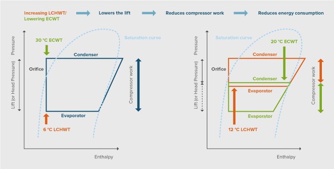
As show in the picture, lowering the Entering Condensing Water Temperature can reduce ‘lift’. Similarly, increasing the Leaving Chilled Water Temperature (i.e., decreasing the ‘load’ on the system) also reduces the lift. Lowering the lift generally increases the efficiency of the chiller (however, depending on the chiller load Vs. efficiency curve).
| Compressor type and capacity | Recommended IPLV (COP) (Part load optimized) | BAT IPLV (COP) (Part load optimized) | Recommended COP (Full load optimized) | BAT (COP) (Full load optimized) |
|---|---|---|---|---|
| Scroll (100 – 200 kW) | 4.08 or more | 4.23 | 2.85 or more | 3.19 |
| Reciprocating (100 – 500 kW) | 3.9 or more | 4.39 | 2.85 or more | 3.51 |
| Screw (200 – 700 kW) | 3.58 or more | 4.23 | 2.85 or more | 3.74 |
| Compressor type and capacity | Recommended IPLV (COP) (Part load optimized) | BAT IPLV (COP) (Part load optimized) | Recommended COP (Full load optimized) | BAT (COP) (Full load optimized) |
|---|---|---|---|---|
| Centrifugal (500 – 1000 kW) | 6.76 | 7.48 | 5.96 | 7.03 |
| Centrifugal (1001 – 7,000 kW) | 7.81 | 9.25 | 6.28 | 7.48 |
| Rotary screw greater than 500 kW | 7.17 | 7.64 | 5.94 | 6.06 |
The choice of the kind of chiller depends on many factors such as the chiller capacity required, usage pattern and operating load conditions, climate, and capital cost being more important ones. In residential sector they are well suited to use in multi dwelling units and high raise apartments where cooling is required most of the time. However, unlike in commercial sector chiller usage for cooling in residential sector is highly uncommon and in its nascent stages. Chiller usage in residential sector is not well documented.
| Chiller type | Application | Drivers |
|---|---|---|
| Centrifugal/Screw | • Typically used in owner occupied and operated buildings • Large offices, typically open plan offices • Hotels • Hospitals |
Equipment cost, Specifications, Life cycle cost |
| Reciprocating/Scroll | • Typically used in rented out buildings • Small commercial buildings • Shopping arcades |
Equipment cost, Specifications, Capital/first cost |
| Scroll/Screw | • Data centres • Process cooling |
Reliability, Redundancy, Precision |
Improvements in chiller and cooling tower systems offer significant savings in energy consumption. Chillers with efficient compressors with magnetic levitation bearing, variable frequency drives for refrigerant flow, heat recovery chillers; improved heat exchangers are some of the best available technolo-gies in the field. Cooling towers with inverter driven multiple speed fans are much more efficient than single speed fans. Some of them are listed below.
There are several types of compressor, each suited to certain capacity ranges and types of application but with significant overlap and selecting the optimum solution is complex. However, the BAT for systems over 200 kW is generally an oil-free centrifugal compressor with magnetic levitation bearings. Cooling energy savings in the range of 30% - 50 % can be achieved by using BAT compressor compared to a typical average compressor.
Description of the technology
Three types of compressor dominate the chiller market in terms of installed capacity: scroll, screw and centrifugal. Each technology has its own size range; best suited type(s) of application and specific design features for best efficiency. Selection of the best compressor type, size and control system for each job is complex and cannot easily be generalised. This will often require a building simulation and detailed inputs about the building, local climate and likely occupation patterns.
Scroll compressors are most common in packaged air conditioners over 12 kW; chillers below 12 kW may use rotary compressors or scroll compressors. On larger systems up to 100 kW, scroll and reciprocating hermetic compressors are used, with scroll and screw compressors competing together up to 200 kW. Larger systems than this are most often based around centrifugal or screw compressors. Centrifugal compressors are very efficient at high and full load.
A key efficiency improvement for any compressor is to match cooling capacity to demand. This can be achieved by various means of short-circuiting or offloading compressors, or through variable speed operation. DC brushless (permanent magnet) motors enable this, and higher motor efficiency. Other improvements include magnetic levitation bearings to reduce friction.
Savings potential
The BAT solution for larger chillers (over 200 kW) is quite clearly a centrifugal chiller with magnetic levitation bearings. The absence of an oil system also considerably improves part load performance leading to savings of between 30% and 50% over conventional chillers.
Variable frequency compressors are the state of the art compressor technology that results in very high efficiency compressor especially at part load conditions. Variable frequency compressors lower the power needed to run the compressor at low load conditions. The load on the compressor is constantly monitored by sensing the chilled water return temperature. As the chilled water return temperature reduces, the load on the chiller also reduces. Variable frequency compressors further increases the efficiency of a chiller compared to a constant speed compressor for a given set of similar conditions. Variable frequency chillers are expected to save approximately 15% - 30 % of chiller energy consumption compared to conventional chillers.

| Chiller type | Positive displacement compressor (air cooled condenser) | Chiller type |
|---|---|---|
| (E.g. 500 kW) | Centrifugal compressor (water cooled condenser) | (E.g. 500 kW) |
| (E.g. 3,500 kW) | (E.g. 3,500 kW) | (E.g. 3,500 kW) |
The choice of heat exchanger type for each system is a complex engineering decision depending up-on capacity, size and budget constraints amongst many others. Microchannel heat exchangers offer significant advantages for most system types, although constraints on their use exist for some applications.
Description of the technology
The type of heat exchanger used in a chiller is determined partly by the capacity but also other system constraints including available space and budget. Shell and tube evaporators dominate the larger end of the market but flat-plate heat exchangers are more compact per kilowatt. Efficiency gains have been shown for some system types, mostly small to medium size systems, through use of microchannel heat exchangers. These are particularly compact and offer advantages of better airflow, significantly higher heat transfer per unit of face area and reduced refrigerant charge. Microchannel heat exchangers offer the BAT solution for most system types but are, however, less applicable to reversible (cooling and heating) systems due to oil return issues.
Savings potential
Microchannel heat exchangers offer a 20% to 40% reduction in refrigerant charge and 10% improved performance for the same face area. Manufacturers claim that heat exchange can be delivered at lower cost than conventional approaches in many situations, although constraints on their use do exist for some applications.
Fan design and matching to applications is complex, but in general the most efficient solutions will have larger fans and variable speed drive to closely match flow with cooling demand.
Description of the technology
A key efficiency improvement is matching capacity (via air flow rate) to cooling demand using inverter driven (variable speed) fans. When less capacity is needed, very substantial energy savings can be made by reducing the fan speed. For example, a 20% reduction in rotational speed yields nearly 50% reduction in energy consumption. For the same pressure and volume, a larger diameter fan is much more efficient than a smaller one - a 10% larger diameter impeller leads to a 41% energy saving. Direct drive between motor and fan avoids the losses associated with belt or other drive types, but power losses do occur in variable speed drive units. Permanent magnet motors offer the most efficient solution.
This applies to fans on fan coil units, condensers (heat rejection equipment), air handling units, air-conditioners and cooling towers. There are very many types of fan with selection dependent upon volume of air delivered, pressure drop, physical size and budget, amongst many other aspects.
Savings potential
Variable speed fans offer around 5% savings in a typical application, but can amount to much more where multiple fans are used in high air volume (i.e. large ducted) applications. Also, optimisation can achieve more than this over a full year.
A chiller not only removes heat from the building but also a chiller compressor adds considerable heat in the process. This heat is often rejected to the atmosphere through condensers. Heat recovery double bundled chillers come with special arrangement to extract this heat rejected and put it to use at some to other point that needs heat. It acts as a combined cooling and heating equipment where there is both heating and cooling demand.
During conditions of low ambient wet-bulb temperature (approx. 10 °C) heat loads in the buildings could be met by the evaporative cooling capacity of the cooling tower. Waterside economizer enables this function by bypassing the chiller function. It is best suited for buildings operating 24/7 such as office spaces and data centres. HVAC Energy savings due to waterside economizer range between 15-40% in cold to moderate warm climates (Stein, 2009).
makes energy efficiency in buildings and appliances transparent. For investors, policy-makers and actors involved in implementation and consultancy. Learn more ...


 Buildings Guide
  Policy Guide
  Appliances Guide
  India
India South Africa